THE MAIN PARTS OF A HYDROGEN FILLING STATION
A hydrogen filling station consists of the following parts:
- Hydrogen storage tank (underground, above ground)
- Compressor
- Heat exchanger
- High-pressure storage tank
- Cooling dosing device
- Dispensing rack
- Filling quick coupler
Hydrogen Storage Tank – The hydrogen that will be filled in the hydrogen filling station is vehicles are most often stored compressed in pressurized storage tanks. Due to the very small hydrogen molecule, it is necessary to select a material for the storage tanks that prevents hydrogen leakage through the material structure. Pressure vessels are most often made of steel or composite materials. In the case of composite containers, a steel or aluminium layer is placed inside the container to prevent hydrogen leakage. The hydrogen is stored in the tanks at a pressure of 200 bar. This hydrogen storage system has been proven and tested for a long time. The disadvantage is the considerable size of the tanks, especially in the case of filling stations that have to serve a large number of vehicles. The pressurised storage tanks can be a fixed part of the filling station and the hydrogen is piped in or transported to the site by trucks and then pumped into the tank. The other option is to use mobile storage tanks, where the hydrogen is filled at the industrial gas filling station and this tank is then transported by road or rail to the filling station. Pressurised steel or composite tanks can be placed on the surface or can be placed underground.
In some cases, it is possible to produce hydrogen on site, most often using electrolysis to produce hydrogen on site, in which case the cost of transporting the hydrogen to the filling station is eliminated.
The following two systems are mainly used for on-site hydrogen storage:
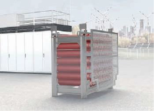
Bulk bundle – a rack containing gas cylinders. All gas cylinders of the bulk bundle are connected to each other by pipes and valves. This concept storage is ideally suited if the system is to be expanded later, as any number of volumes can be connected. Very small quantities can also be stored with this concept.
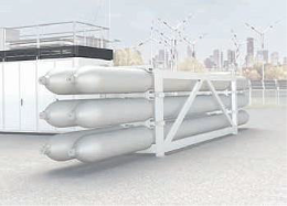
Tubular storage tank – these storage tanks consist of long storage units that are installed in a frame. A tubular storage unit is 6 or 12 metres long and can store large quantities of hydrogen.
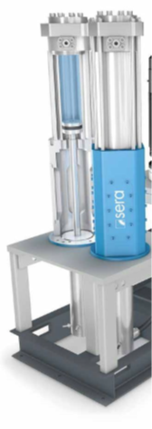
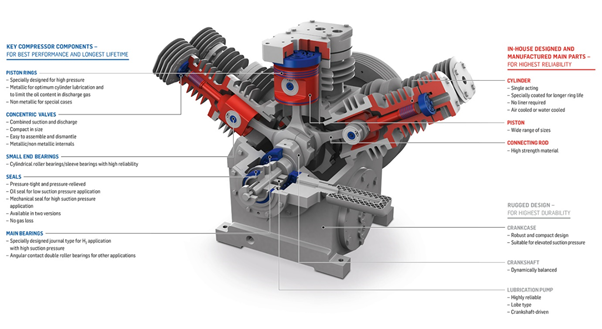
Compressor – The compressor compresses the hydrogen to increase pressure and reduce volume, allowing more hydrogen to be stored in the system and for the gas to flow efficiently for dispensing. [22] At high-pressure filling (700 bar), the compressor is required to pressurize the hydrogen to about 950 bar. [23] At medium pressure filling, the hydrogen is compressed to a pressure of about 530 bar. [23] Dry-chain piston compressors with electro-hydrostatic drive are used for hydrogen compression. The compressor unit consists of two coaxial, vertical gas cylinders, each mechanically coupled and driven by a hydraulic cylinder. The space between the gas and drive cylinders prevents contamination of the medium with hydraulic oil.
The two drive cylinders are hydraulically connected to each other. Changes in stroke direction are made by contactless switches and the hydraulic cylinders are driven by a hydraulic power pack. When using a system with a control pump, the change in piston stroke can be infinitely controlled. Electro-hydrostatically driven dry-running reciprocating compressors compress gases such as hydrogen, nitrogen, helium, argon or ethylene completely free of lubricants and solids. The special arrangement and design of the gas piston seals and guide elements also makes it possible to dispense completely with the usual lubrication of the seal components in high and peak pressure applications.
Heat exchanger – during the compression process, hydrogen is unwantedly heated, so the highly compressed hydrogen must pass through a heat exchanger where it is cooled.
High-pressure tank – The highly compressed gas is stored in a tank where it is ready to be filled into the vehicle. Storage is controlled by specially designed valves, fittings and electrical controls designed to regulate pressure and interact with the dispensing equipment and vehicle as required. [22]
Refrigerated dispensing equipment – For filling, the hydrogen is cooled to -40°C for fast and efficient filling to ensure safe hydrogen dispensing and compliance with filling protocols, i.e. J2601 protocol.
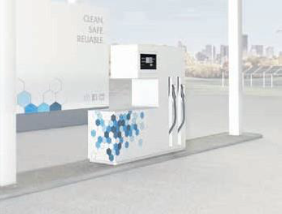
Dispensing Rack – Serves the same purpose as the dispensing rack on a conventional fueling station. Includes fill coupling, fill hose, display and control technology. The payment terminal can be located separately. Using the display, the user can conveniently start the refuelling process. A short step-by-step instruction is then followed until the filling coupling is firmly attached to the fuel filler neck of the vehicle. Hydrogen at temperatures down to -40 °C then flows through the filling coupling into the vehicle's hydrogen tank. The dispensing unit can fill the vehicle tank with a pressure of both 350 bar and 700 bar. [20]
The dispensers shall be installed in the open air under a shelter made of non-combustible materials, including roofing. They shall be located so that they are easily visible from the hydrogen filling station operator's position or controllable by CCTV and so that vehicles do not pass through the hazardous areas surrounding them. The shelter shall be designed for a wind speed of 160 km/h and a roof snow load of 100 kg/m², taking into account seismic resistance.
Filling quick coupler – connects the dispensing equipment and the filled vehicle. It shall provide a filling pressure resolution of 350 bar or 700 bar. For filling connections only filling hoses may be used, the design of which ensures a conductive connection to the mobile filling device, withstands hydrogen flow and operating pressure. The filling connection shall be no shorter than 3 m and no longer than 5 m. The design of the filling quick coupling shall preclude its use for purposes other than filling the tanks of hydrogen mobile equipment. Furthermore, it shall ensure that the hydrogen flow is only open when it is tightly connected to the filling connection of the mobile equipment and shall exclude unintentional disconnection. Disconnection of the filling quick coupling shall be possible only after depressurisation. If the mechanical stress exceeds a certain limit, it will disconnect and close the hydrogen supply from the dispenser and the hydrogen return flow from the tank of the mobile equipment being filled. The force required to disconnect is substantially less than the tensile strength of the filling connection hose or the force required to pull the filling quick coupling or damage the dispensing device. [24] The filling quick coupling shall allow a sufficiently fast gas flow for the shortest possible filling time of the vehicle and shall also allow data linking of the filled vehicle and the dispensing device to ensure data communication and optimum setting of the filling mode.